12 Channel Rf Remote Control Circuit Diagram

12 Channel Dc Remote Control Switch Rf Transmitter Receiver 12 Control Modes 0020204 S12ca Dc09 X2f 12 X2f 24 Cv 12 Remote Control Automotive Electrical

12 Channel Dc Remote Control Switch Rf Transmitter Receiver 12 Control Modes 0020204 S12ca Dc09 X2f 12 X2f 24 Cv 12 Remote Control Automotive Electrical

Rf Remote Control Circuit For Home Appliances Without Microcontroller Home Appliances Home Automation System Diy Home Security

Rf Remote Control Circuit For Home Appliances Without Microcontroller Home Appliances Home Automation System Diy Home Security

Making A 4 Channel Rf Remote Pcb Design Included Gadgetronicx Pcb Design Remote 4 Channel

Making A 4 Channel Rf Remote Pcb Design Included Gadgetronicx Pcb Design Remote 4 Channel

2 Channel Rf Remote Control Remote Control Remote Control

2 Channel Rf Remote Control Remote Control Remote Control

Making A 4 Channel Rf Remote Pcb Design Included Gadgetronicx Remote Pcb Design Wireless Transmitter

Making A 4 Channel Rf Remote Pcb Design Included Gadgetronicx Remote Pcb Design Wireless Transmitter

Circuit Diagram Circuit Diagram Remote Control Circuit

Circuit Diagram Circuit Diagram Remote Control Circuit

Circuit Diagram Circuit Diagram Remote Control Circuit

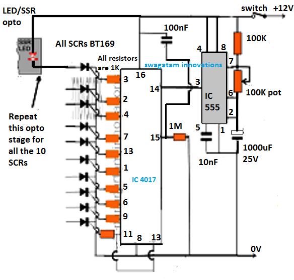
We have used ic 4017 to convert it into a push on push off switch.

12 channel rf remote control circuit diagram.

The basic small range remote controls are 2 infrared and rf radio frequency. Works for longer distances as compared to ir. Rf remote control circuit designed with 434 mhz ask amplitude shift keying transmitter and receiver here ic ht12e act as encoder and ic ht12d act as decoder this circuit is constructed with easy available components. One of the weaks of infrared is that the signal can not pass the walls.

This current is given to the inverting input of 3130 ic which will get triggered by this current and give amplified output. Used for remote control applications like burglar alarm car door alarm calling bell security systems etc. Circuit diagram of infrared remote control switch. This project has two stages that is 1.

Rf remote control circuit advantages. Receiver circuit is connected to ac appliance via relay so that we can control the light remotely. In this remote controlled switch circuit we are using tv remote to on off the ac light by pressing any button of remote and using the tsop1738 at receiver end. The circuit transmitter and receiver use few components and ordinary i love few component circuits.

So if you want to control your garage door the only way is to use some rf remote control. Push buttons 3 nos. In the receiver section there are 3 photodiodes which will detect the infrared signals from the receiver and produce leakage current to the capacitor c1. Rf signals can travel even there is an obstruction between transmitter and receiver.

Limitations of the circuit. It can install with a toy train or automobile that used a voltage supply from 6 12 volts. In this project a remote has. Rf remote control circuit applications.

Which the radio receivers sectors is installed in the car will turn on off the dc motor runs by forcing the rhythm on off of the transmitter radioinstead of using a switch turns on off in the car. This remote gives approximately 150 meter coverage by extending the ariel wire it can be increased up to 200 meters. This small rf remote control or radio control rc circuit is easliy. Making a 433 mhz 315 mhz rf remote control with relay flip flop.

Remote control circuit through radio frequency without microcontroller description this is a simple type remote control by using rf communication without microcontroller. 433 mhz rf transmitter and receiver. 433mhz universal wireless remote control switch dc 12v 1ch relay receiver module and rf transmitter 433 mhz remote controls 1527 with 2 button from.

Remote Control Circuit With Ir Envirementalb Com In 2020 Circuit Diagram Remote Control Remote

Remote Control Circuit With Ir Envirementalb Com In 2020 Circuit Diagram Remote Control Remote

Multi Channel Remote Control System Control System Remote Control Electronics Circuit

Multi Channel Remote Control System Control System Remote Control Electronics Circuit

Ir Remote Control On Off Switch Circuit Circuit Remote Control Electrical Circuit Diagram

Ir Remote Control On Off Switch Circuit Circuit Remote Control Electrical Circuit Diagram

In This Article We Elaborately Learn To Make A 2 4ghz 10 Channel Remote Control Switch Circuit Circuit Projects Electronic Circuit Projects Electrical Gadgets

In This Article We Elaborately Learn To Make A 2 4ghz 10 Channel Remote Control Switch Circuit Circuit Projects Electronic Circuit Projects Electrical Gadgets

Source : pinterest.com